A. Is your device compatible with my boat?
1. Will your device work on my new 40-foot boat?
Yes. Yachts of this class are equipped with digital sensors (e.g. depth sounder, speed/log, anemometer), autopilot, AIS, digital instruments and chartplotters. Most of them are connected by a NMEA 2000 network (or one of its branded versions: Raymarine SeaTalk NG, Furuno CAN, or Simrad SimNet). Our devices are compatible with the NMEA 2000 network and its branded versions (adaptor cable may be required in some cases).
2. Will your device work on my old 40-foot boat?
Our devices are designed for NMEA 2000 networks (except NMEA 0183 Multiplexer, NMEA 0183 to NMEA 2000 gateway, NMEA 2000 Wi-Fi Router, NMEA 0183 Wi-Fi Router and NMEA 0183 Wi-Fi Gateway). The standard was released in 2000, but compatible devices became widely available on the market 5 or more years later. For example, the A-Series (presented in 2006) of Raymarine chartplotters has no NMEA 2000 support, the C-Series Classic (2006) has limited support of NMEA 2000 (SeaTalk2 interface), and the C-Series Widescreen (2008) is fully compatible with NMEA 2000 (SeaTalk NG interface).
So, if your chartplotter and digital instruments were manufactured before 2005, they are compatible with our NMEA 0183 and SeaTalk devices only. Chartplotters and digital instruments manufactured between 2006-2008 may be compatible with our NMEA 2000 devices. Most chartplotters manufactured after 2008 are compatible.
Our NMEA 0183 Gateway allows you to connect NMEA 0183 equipment to a NMEA 2000 network and vice versa. It has a bi-directional converter with wide support of message types including AIS and autopilot.
NMEA 0183 Wi-Fi Gateway allows you to see data from an NMEA 0183 marine devices on a PC or smartphone. It is compatible with virtually all marine software.
NMEA 0183 Wi-Fi Router is a smart NMEA 0183 and SeaTalk multiplexer which also allows you to see data from marine devices on a PC or smartphone. It has four NMEA 0183 ports and one SeaTalk port.
NMEA 2000 Wi-Fi Router is equipped with NMEA 2000 and SeaTalk ports, two NMEA 0183 ports, has three TCP/UDP data servers and a built-in web server, where you can easily configure it or update the firmware. It connects all marine and mobile devices easily and supports all popular marine protocols.
3. Will your device work on my 20-foot boat?
Small boats may be equipped with simple small-screen models of chartplotters which may have limited connectivity possibilities. Small boats may not have sensors or other digital equipment except chartplotters, so they may not have an installed network. The answer is maybe.
B. Installation and connectors
2. I do not have an NMEA 2000 network on my vessel, how to install it?
We recommend installing a new network with NMEA 2000 Micro Male connectors.
Simrad SimNet (with yellow backbone connectors) and Raymarine SeaTalk NG (with blue and white connectors) are still popular, but those companies are starting to use NMEA 2000 Micro Male connectors in recent equipment models.
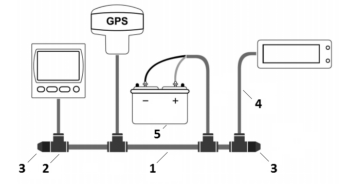
Figure 1. Basic NMEA 2000 network layout
A NMEA 2000 network's main components are: (1) backbone cable, (2) T-connectors, (3) two terminator resistors, (4) spur or "drop" cables, (5) DC power source.
NMEA 2000 equipment can be connected either directly to a T-connector or with a spur cable.
The main difference between Garmin NMEA 2000, Raymarine SeaTalk NG and Simrad SimNet is the connector type.
Please refer to the manufacturer's documentation for a comprehensive installation guide:
Those guides cover basic network architecture overview, a list of available cables, terminators and connectors, technical requirements and practical examples for building a NMEA 2000 network.
You can order a NMEA 2000 Starter Kit, for example Garmin NMEA 2000 Starter Kit or Raymarine SeaTalk NG Starter Kit.
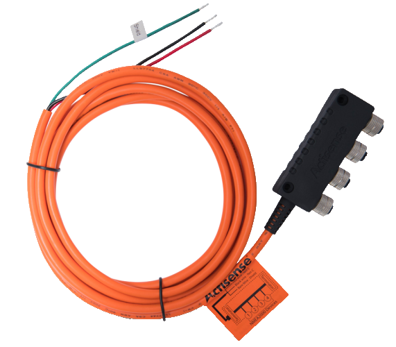
Figure 2. ActiSense SBN
For a small network, we recommend ActiSense SBN. It has four NMEA 2000 connectors, terminators inside, and 3m power cable. You only need to connect it to 12V battery.
3. What type of device connector is suitable for my boat?
Our devices are supplied with different types of NMEA 2000 connectors. Models with the suffix R at the end of model name are equipped with NMEA 2000 connectors compatible with Raymarine SeaTalk NG. Models with the suffix N are equipped with NMEA 2000 Micro Male connectors.
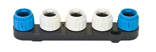
Figure 2. Raymarine SeaTalk NG proprietary connectors on a 5-Way Connector
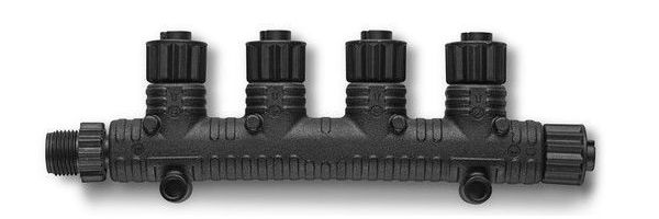
Figure 3. NMEA 2000 Micro Male connectors on a multi-port T-connector
If you have Raymarine equipment, choose the SeaTalk NG connector (Fig. 2.). In the case of Garmin equipment, choose the NMEA 2000 Micro Male connector (Fig. 3.).
For other network types, choose the device with NMEA 2000 Micro Male connector, because all manufacturers have an adaptor cables from NMEA 2000 Micro to their proprietary connectors.
For example, to connect our device to a Simrad SimNet network (Fig. 4.) you can use an adaptor cable (SimNet Female — NMEA 2000 Micro Female, i.e. Navico part number 24006199).
Figure 4. Simrad SimNet proprietary connectors on a 7 Prong Multi-Joiner
It is also possible to connect our device with NMEA 2000 Micro Male connector to Raymarine SeaTalk NG network using an adaptor cable (Raymarine part numbers A06045 or A06075).
4. Is it hard to install the device?
No. Our devices are plug and play. Turn off the power of the NMEA 2000 network, find a free connector, connect the device, and turn the power on. The Device's LED will flash. In most use cases, no additional configuration of device is required.
5. How can I be sure that your N2K device is compatible with my equipment?
All our devices are compatible with NMEA 2000 networks.
To check if your equipment is NMEA 2000-compatible, check the installation manual (and/or user manual) supplied with your equipment. First, make sure that it contains some mention of NMEA 2000 (or a branded version of NMEA 2000: SeaTalk NG, Furuno CAN, or Simrad SimNet).
To check if our device data can be interpreted by a particular piece of equipment, refer to the documentation for your equipment:
- check the supported PGN list in your equipment documentation, then compare it with our device's supported PGN list given in the appendix of the corresponding user manual,
- if your equipment documentation lacks a PGN list, check which data types are available for display and/or processing. For example, some legacy models of chartplotters lack the ability to show humidity data.
If in doubt, please refer to our technical support and specify exact model(s) of your equipment.
6. When should I use a model with a terminator (with index T at the end of model name)?
According to the specification, an NMEA 2000 network has two terminators (120-Ohm resistors) connected to the NMEA 2000 backbone endpoints. Device models with the T index at the end of their names contain a built-in terminator and should be connected to the network instead of the terminator. This allows zero-cost connection of the Devices to existing networks that have no free connectors. Sometimes it is hard to find the end of the bus and terminator on large vessels.
Note: models with built-in terminators are available for the Barometer and Thermometer and not available for other products.
7. I have no free NMEA 2000 connectors on my vessel, how can I connect the device?
For networks with NMEA 2000 Micro connectors, you should buy one T-connector from any manufacturer, for example, Garmin part number 010-11078-00. If more than one device connection is required, you may buy a multi-port T-connector (see Fig.3), for example, Garmin part number 010-11078-01 or Navico part number 000-12612-001.
For networks with SeaTalk NG connectors, you should buy one T-connector (Raymarine part number A06028) and one backbone cable (Raymarine part number A06033). If more than one device connection is required, you may buy a 5-Way Connector (see Fig. 2, Raymarine part number A06064).
An alternative option is available for our Barometer and Thermometer which can be supplied with a built-in terminator (models with T suffix at the end of their name). They can be installed on the network backbone endpoints instead of terminator.
8. My equipment has a connector labeled "NMEA". Is it compatible?
In most cases, this indicates an NMEA 0183 connector, not NMEA 2000.
Device which can be connected to NMEA 0183 are NMEA 0183 Gateway YDNG-03 (allows you to connect NMEA 0183 equipment to a NMEA 2000 network and vice versa), NMEA 0183 Wi-Fi Gateway (allows you to see data from an NMEA 0183 marine devices on a PC or smartphone), NMEA 2000 Wi-Fi Router (has NMEA 0183, NMEA 2000, SeaTalk ports and Wi-Fi), NMEA 0183 Wi-Fi Router and NMEA 0183 Multiplexer.
Other devices are compatible with NMEA 2000 only.
C. Networks and protocols
1. Are your devices compatible with Raymarine SeaTalk 2?
Yes. SeaTalk 2 is an earlier version of SeaTalk NG with a proprietary connector type and is NMEA 2000 compatible.
ST2 Adaptor Cable (Raymarine part number A06048) should be used to join SeaTalk 2 and SeaTalk NG into single network.
To connect a Raymarine E-Series Classic display to a SeaTalk NG network, use Raymarine cable part number A06061.
2. Are your devices compatible with Raymarine SeaTalk HS interface?
No. Our devices are compatible with SeaTalk NG, SeaTalk 2 and SeaTalk (SeaTalk 1) only and not compatible with SeaTalk HS. SeaTalk HS (High-Speed) is based on Ethernet technology and designed for connection of radars and fish finders.
3. Are your devices compatible with Raymarine SeaTalk?
NMEA 0183 Wi-Fi Router is a smart NMEA 0183 and SeaTalk multiplexer which also allows you to see data from marine devices on a PC or smartphone. It has four NMEA 0183 ports and one SeaTalk port.
NMEA 0183 Multiplexer has five NMEA 0183 ports and SeaTalk port.
NMEA 2000 Wi-Fi Router is equipped with NMEA 2000 and SeaTalk ports, two NMEA 0183 ports, has three TCP/UDP data servers and a built-in web server, where you can easily configure it or update the firmware. It connects all marine and mobile devices easily and supports all popular marine protocols.
4. Are your devices compatible with NMEA 0183?
Our NMEA 0183 Gateway YDNG-03 allows you to connect NMEA 0183 equipment to a NMEA 2000 network and vice versa. It has a bi-directional converter with wide support of message types including AIS and autopilot.
NMEA 0183 Wi-Fi Gateway allows you to see data from an NMEA 0183 marine devices on a PC or smartphone.
NMEA 0183 Wi-Fi Router is a smart NMEA 0183 and SeaTalk multiplexer which also allows you to see data from marine devices on a PC or smartphone. It has four NMEA 0183 ports and one SeaTalk port.
NMEA 0183 Multiplexer has five NMEA 0183 ports and SeaTalk port.
NMEA 2000 Wi-Fi Router is equipped with NMEA 2000 and SeaTalk ports, two NMEA 0183 ports, has three TCP/UDP data servers and a built-in web server, where you can easily configure it or update the firmware. It connects all marine and mobile devices easily and supports all popular marine protocols.
NMEA 2000 Wi-Fi Gateway YDWG-02 and USB Gateway YDNU-02 has no physical NMEA 0183 connections, but they can translate NMEA 2000 data to NMEA 0183 (and vice versa). Translated data are available for software applications by TCP and UDP network protocols over Wi-Fi or from a serial (COM) port.
D. NMEA 2000 sensors
1. How could I measure a sea temperature with Thermometer YDTC-13?
YDTC-13 Thermometer has a sealed digital sensor which can be mounted through-hull with a DIY thermal connector interface. The installation example is available here.
The case of a digital sensor is waterproof. The sensor cable can be extended up to 100 meter (328 feet) with a three-conductor wire.
2. Can your sensors show measurements in a graph form?
Our sensors send only a measurement results. Data presentation depends on the software capabilities of the chartplotter and digital navigation instruments. Please refer to your equipment documentation to confirm if it is able to display data on pressure, temperature and humidity as a graph.
All sensors are store measurements of the last 48 hours (with 1-minute intervals) in the RAM, except the Humidity Sensor, which stores only 24 hours of data, but humidity and air temperature both. And the last 4 minutes of all data types are stored with a 2-second interval. This data can be retrieved by compatible software or hardware.
The Web Gauges of Wi-Fi Gateway YDWG-02 has a barograph, which can show barometer measurements in the form of the graph.
3. Can your devices send data with high resolution?
Thermometer always sends data with 0.01°C resolution.
Humidity sensor sends humidity data with 0.004% resolution, temperature data with 0.01°C resolution.
Barometer sends data with: 1.0 hPa (mbar) resolution using PGN 130310 and 130311 (NMEA 2000 Version 2); 0.01 hPa (mbar) resolution using PGN 130314 (NMEA 2000 Version 3). Your equipment must support NMEA 2000 message with PGN 130314 "Actual Pressure" if it is compatible with NMEA 2000 Version 3.
If your equipment displays data with lower resolution, it may be due to an outdated or poorly designed software of your display or chartplotter.
E. Operation of the Voyage Recorder
1. Are all data of my equipment recorded?
Yes. If your equipment is connected to the NMEA 2000 network, a Voyage Recorder will save all available NMEA 2000 network data to a MicroSD card. It does not analyze any data, leaving that work for the software application to be run later on personal computer. Because of that, the Voyage Recorder supports all messages broadcasted through the network and is compatible with any equipment present on the vessel's network.
Note that the PC Converter software (YDVRConv, you can download and try it) does not support all types of NMEA 2000 network messages and especially proprietary. Therefore, your data may be recorded by Voyage Recorder, but not decoded by PC Converter software.
2. Can support of my equipment's data be added to the PC Converter?
We extend the list of supported NMEA 2000 messages in each program update. But some messages are proprietary, neither covered by NMEA 2000 standard nor documented. Please send your recordings to us with the photos of your instruments and we will investigate your case.
If the improvements required can be beneficial to other users, we will do it for free.
3. How to choose a MicroSD card and prepare it for operation?
Our devices support MicroSD memory cards of all sizes and classes. MicroSD Class 10 or higher cards are recommended for use with the Voyage Recorder.
Our devices support FAT (FAT12, FAT16, MS-DOS) and FAT32 file systems and do not support exFAT, NTFS, or any other file systems.
Please note that on Windows platform there is an issue, as you cannot select the FAT32 file system for memory cards of 64 GB capacity or more in the formatting program supplied with the operating system.Third-party freeware formatting program can be used to format large cards under Windows (download with graphical user interace or console version). Linux and Mac OS X have no issues.
4. What does "No points were added to the vessel track..." error of PC Converter mean?
This problem may arise when you are converting data to CSV output format and the recording has no time data or to GPX output format or if the recording has no time and/or GPS position data.
In case of GPX output format, there is no solution. Track points must have geo coordinates, and the program cannot generate the track if GPS coordinates are not available.
In general, Voyage Recorder and PC software are designed to record voyages, and coordinates and time must be present on the network. But some of our customers are using Voyage Recorder to record data in the lab or for diagnostic purposes (for example, engine data only).
You have the following options to process data without time data using Voyager Recorder PC software:
- 1) convert data to .CAN format to view it with CAN Log Viewer software;
- 2) convert to OpenSkipper .XML to view it with log viewer of OpenSkipper;
- 3) convert to Canboat / Signal K LOG file to process it with your own script (if you are programmer and familiar with NMEA 2000);
- 4) restore timeline and convert data to CSV format.
The last method allows you to create a CSV output file with your data. Messages stored in your recordings have internal time, but the software must have at least one "real time" record to restore the time line and generate CSV file.
Download FAKEDATE.DAT and place it in the folder with your data. In the command line of your operating system, type the following command:
YDVRConv /join FAKEDATE.DAT 00010001.DAT 00010002.DAT OUTPUT.DAT
Where 00010001.DAT and 00010002.DAT are your files in chronological order, you can specify one or multiple files to join with FAKEDATE.DAT. The program will generate OUTPUT.DAT file, which will contains data from all files specified between /join key and output file name.
The output file can be processed by PC software of Voyage Recorder to generate spreadsheet (CSV) file with your network data decoded. If necessary, you can replace the fake date with a real date in a spreadsheet. It is also possible to modify FAKEDATE.DAT, but this way is trickier.
5. What data types are suppored by PC software?
Please, see the list of data types are available in .GPX (tracks) and .CSV (spreadsheet) output files here.
F. Operation of the J1939 Engine Gateway
1. Do I need two gateways for a twin engine setup?
If the engines are connected to a single network (joined with a sync cable), one gateway is adequate for transferring data from all engines to the NMEA 2000 network. The gateway supports up to 8 engines on a network. If the engines are not united on a single network, a separate gateway will be needed for each one.
In case of the EVC system, the basic test is to switch the cables of the EVC tachometers. If the port tachometer shows data of the starboard engine, it means that you need a dedicated gateway for each engine (it is less expensive than installing a sync cable). If the port tachometer shows port engine data, then one gateway is enough.
2. Can I connect my engines with a sync cable?
In case of separate engine installations, both engines have the same J1939 address (0). To work in a single network (if your engines support it), the starboard engine should have a different J1939 address (1). At the very least, you will need to update the starboard engine firmware, and in some cases update the firmware for the engine instruments. This procedure is expensive; a second gateway installation is more practical.
3. What J1939 data are converted by Engine Gateway?
| PGN |
SPN |
Description |
| 60160 |
- |
Transport Protocol - Data Transfer |
| 60416 |
- |
Transport Protocol - Connection Mgmt |
| 61443 |
92 |
Electronic Engine Controller 2 / Engine Percent Load At Current Speed |
| 61444 |
190 |
Electronic Engine Controller 1 / Engine Speed |
| 61444 |
513 |
Electronic Engine Controller 1 / Actual Engine - Percent Torque |
| 61445 |
523 |
Electronic Transmission Controller 2 / Current Gear |
| 65226 |
- |
Active Diagnostic Trouble Codes |
| 65253 |
247 |
Engine Hours, Revolutions / Engine Total Hours of Operation |
| 65262 |
110 |
Engine Temperature 1 / Engine Coolant Temperature |
| 65262 |
175 |
Engine Temperature 1 / Engine Oil Temperature 1 |
| 65263 |
94 |
Engine Fluid Level / Pressure 1 / Engine Fuel Delivery Pressure |
| 65263 |
100 |
Engine Fluid Level / Pressure 1 / Engine Oil Pressure |
| 65263 |
109 |
Engine Fluid Level / Pressure 1 / Engine Coolant Pressure |
| 65266 |
183 |
Fuel Economy (Liquid) / Engine Fuel Rate |
| 65270 |
102 |
Inlet / Exhaust Conditions 1 / Engine Intake Manifold #1 Pressure |
| 65270 |
173 |
Inlet / Exhaust Conditions 1 / Exhaust Gas Temperature |
| 65271 |
158 |
Vehicle Electrical Power 1 / Keyswitch Battery Potential |
| 65271 |
167 |
Vehicle Electrical Power 1 / Charging System Potential (Voltage) |
| 65271 |
115 |
Vehicle Electrical Power 1 / Alternator Current |
| 65271 |
168 |
Vehicle Electrical Power 1 / Battery Potential / Power Input 1 |
| 65271 |
114 |
Vehicle Electrical Power 1 / Net Battery Current |
| 65272 |
127 |
Transmission Fluids / Transmission Oil Pressure |
| 65272 |
177 |
Transmission Fluids / Transmission Oil Temperature |
| 65276 |
38 |
Dash Display / Fuel Level 2 |
| 65276 |
96 |
Dash Display / Fuel Level 1 |
| 65279 |
97 |
Water in Fuel Indicator |
| 65373 |
- |
Volvo Penta proprietary (engine tilt/trim) |
| 65417 |
- |
Volvo Penta proprietary (alerts of MDI block) |
Note: data you may get on the chart plotter depends on the engine controller and number of installed sensors; legacy chart plotters may not support display of all data types.
4. How to check my Volvo Penta engine is compatible?
Your engine is compatible if your tachometer is connected with a 6-pin "Deutsch" connector (Fig. 5.). No adaptor cable required in this case.
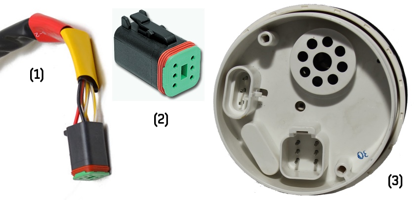
Figure 5. (1) cable, (2) connector, (3) EVC tachometer (back view).
Your engine is compatible if you have a 6-pin "Multilink" connector on your MDI (Mechanical Diesel Interface) box, HCU (Helm Control Unit) or HIU (Helm Interface Unit) block (with a yellow label, see Figure 6).
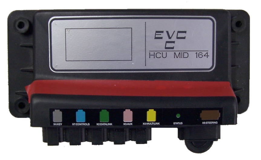
Figure 6. EVC block with Multilink connector (with yellow label).
If you have aluminum HCU (with 12-pin yellow labeled "Multilink" connector) as shown at Figure 7, an "EVC-A EC 12-pin X5:MULTILINK" adaptor cable is required.
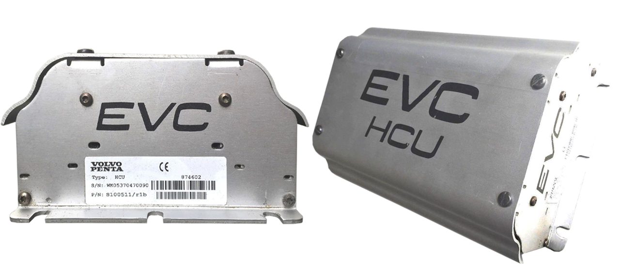
Figure 7. EVC-A EC HCU (Helm Control Unit).
If there is no "Multilink" connector, but there is yellow-labled "C4" connector and a 12-pin gray "C5:ENGINE" or "C5" connector on the HIU (Figure 8), an "EVC-A MC 12-pin C5:ENGINE" adaptor cable is required.
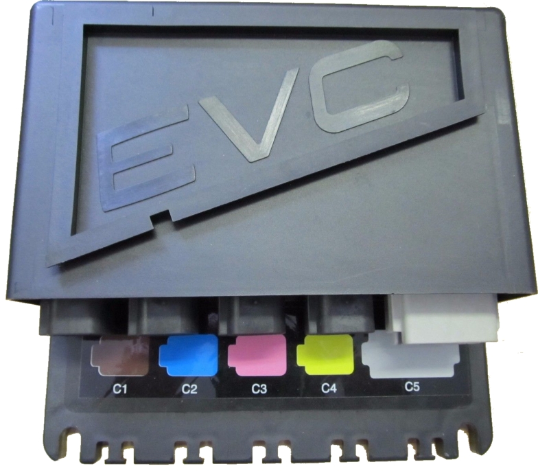
Figure 8. EVC-A MC HIU (Helm Interface Unit).
In other cases, please please refer to section IV of manual or contact us.
5. Will the fuel rate of my Volvo Penta engine be available?
Yes, if you are able to observe it on any of your engine instruments.
If you do not have an engine instrument which can display the fuel rate, please check whether your engine documentation mentions "Trip Computer" software.
It is notable that for a period in 2005–2006, Volvo decided not to transmit fuel rate from the ECU unless an additional firmware upgrade called "Trip Computer" is installed. This upgrade can be performed only by a certified Volvo technician and costs around USD $600 per engine (including labor costs).
If your engine happens to fall into this category, there is no way to get the fuel rate by any gateway simply because there are no fuel rate data available on the engine CAN network.
Later, Volvo abandoned this idea and made fuel rate available again.
6. What is the purpose of the plug supplied with YDEG-04 gateway?
The purpose of the plug is to connect two CAN buses of a multilink interface, which is necessary for the engine network to function properly. This plug is not a CAN bus terminator.
If you are installing the Gateway in place of a broken EVC tachometer or connecting the gateway to the Multilink port where no other devices or cables are connected, the plug supplied with the Device must be installed in the unused connector of the Device. In other cases, the plug can be used as a dust cap.
The YDEG-04 gateway is supplied with a male plug in the default configuration. A male plug is used if the gateway is installed as the last device connected to an "EVC bus" cable, for example, as a replacement of a broken EVC tachometer.
A female plug is used if the gateway connects directly to a free "Multilink" port of the HCU (not in series with any of the existing "Multilink" connections). If you need a female plug, please contact us before placing an order.
If you have received the wrong plug type, you can either ask us for a free plug of the correct type or rewire the free YDEG-04 connector. You should disassemble the 6-pin "Deutsch" connector of the Y-piece and connect the wires directly, preferably by crimping or with cable terminals: pin 1 (green or blue wire) to pin 2 (brown wire) and pin 3 (yellow wire) to pin 5 (white wire).
7. How can I be sure that the J1939 interface of my engine is healthy?
First check the power supply voltage. Turn the ignition ON and check the voltage on the engine connector. You should measure the voltage between the pins of the engine connector which is connected to pin 6 and pin 4 of the 6-pin Deutsch connector of the YDEG-04 engine gateway (directly or via an adaptor cable). Pin 6 should have between +10 and +30 V potential with respect to pin 4.
Then check the CAN bus termination. Turn the ignition OFF and check the resistance of the CAN bus on the engine connector. You should measure the resistance between the pins on an engine connector which is connected to pin 1 and pin 3 of the 6-pin Deutsch connector of the YDEG-04 engine gateway (directly or via an adaptor cable). The resistance should be 60 .. 120 Ohm.
8. How to be sure that the J1939 interface of the gateway is healthy?
YDEG-04 has a galvanically isolated CAN transceiver which is powered from the engine side. You can check whether the transceiver has an electrical fault in the following way.
First check the CAN transceiver power consumption. Connect the power source (+12 to +30 V) in series with an ammeter to the YDEG-04 6-pin Deutsch connector, (+) to pin 6, (-) to pin 4 (Fig. 9).
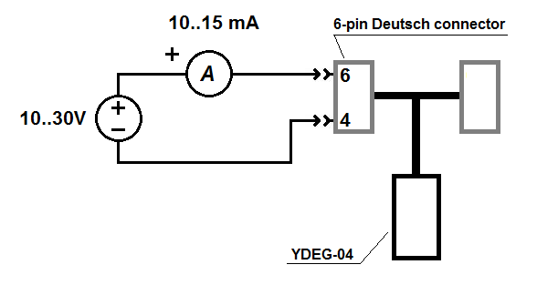
Figure 9. YDEG-04 test circuit for measuring transceiver current consumption
The nominal current consumption should be 10–15 mA. Over- and undercurrent indicates a transceiver fault, no current at all may also indicate a connection wire fault.
Then check the CAN circuitry input resistance. No power should be applied to YDEG-04 while performing this measurement; the gateway must be disconnected from the J1939 network.
Measure the resistance between pins 3 and 1 on YDEG-04 6-pin Deutsch connector (Fig. 10).
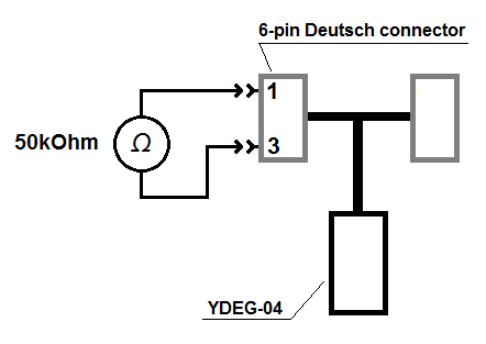
Figure 10. YDEG-04 test circuit for measuring transceiver input resistance
The nominal resistance should be ~50 kOhm. Other values indicate a transceiver fault or a connection wire fault.
9. What SmartCraft data are converted by Engine Gateway?
To activate the SmartCraft protocol (used in Mercury and Mercruiser engines) in the Gateway, you should upload the configuration file YDEG.TXT with only one line: SMARTCRAFT=ON. This is enough for boats with one or two engines. For your convenience, we prepared a configuration file optimized for SmartCraft.
| SmartCraft Data |
NMEA 2000 PGN, Data Field [bit] |
| Engine Revolutions, RPM |
127488, Engine Speed, RPM |
| Boost Pressure (Diesel) |
127488, Engine Boost Pressure |
| Manifold Pressure (Gas) |
127488, Engine Boost Pressure |
| Trim Position |
127488, Engine Tilt/Trim |
| Oil Pressure |
127489, Engine Oil Pressure |
| Oil Temperature |
127489, Engine Oil Temperature |
| Coolant Temperature |
127489, Engine Temperature |
| Battery Voltage |
127489, Alternator Potential |
| Fuel Flow |
127489, Fuel Rate |
| Engine Run Time |
127489, Total Engine Hours |
| Block/Water Pressure |
127489, Coolant Pressure |
| Fuel Pressure |
127489, Fuel Pressure |
| Warn: Check Engine |
127489, Engine Status [1] |
| Warn: Overheat |
127489, Engine Status [2] |
| Warn: Low Oil Pressure |
127489, Engine Status [3] |
| Warn: Low Oil Remote |
127489, Engine Status [4] |
| Warn: Low Oil Reserve |
127489, Engine Status [4] |
| Warn: Low Voltage |
127489, Engine Status [6] |
| Warn: Low Block Pressure |
127489, Engine Status [8] |
| Warn: Guardian Active |
127489, Engine Status [19] |
| Warn: Water In Fuel |
127489, Engine Status [9] |
| Warn: Overspeed |
127489, Engine Status [13] |
| Fault: Check Engine/Guardian |
127489, Engine Status [1] |
| Fault: CAN |
127489, Engine Status [21] |
| Engine Load (Diesel) |
127489, Percent Engine Load |
| Gear Pressure |
127493, Transmission Oil Pressure |
| Gear Temperature |
127493, Transmission Oil Temperature |
| Intake Mainfold Temperaure |
130316, Actual Temperature |
| Fuel Level 1 |
127505, Fluid Level |
| Fuel Level 2 |
127505, Fluid Level |
| Battery Voltage |
127508, Battery Voltage |
Note: data you may get on the chart plotter depends on the engine controller and number of installed sensors; legacy chart plotters may not support display of all data types.
Z. Other questions
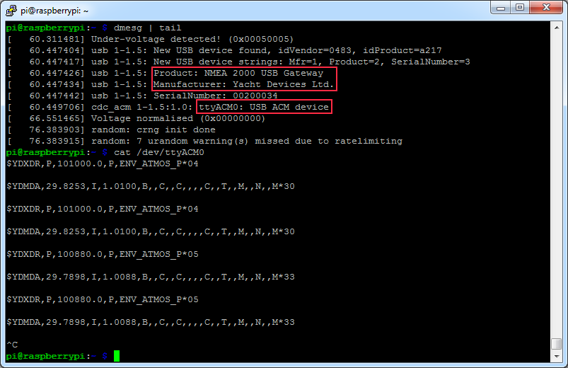
1. Is the USB Gateway compatible with a Raspberry Pi?
Yes. No drivers are reqired. You only need to connect the NMEA 2000 USB Gateway to USB port of your Raspberry Pi.
2. What data are converting between NMEA 2000 and NMEA 0183?
It looks like our gateways (USB, 0183/2000, NMEA 2000 Wi-Fi) are winning, having the widest range of supported messages. You can find the full conversion table in product's manual.
In the table below (updated on Feb 17, 2019) you can find the list of conversions available in our gateways, the gateways of ActiSense and Maretron (data source is available through the link in the header) as well as the list of supported messages in the popular iNavx application.
NMEA 0183
Sentence |
YD Products |
Actisense NGW-1-AIS |
Actisense NGW-1 |
Maretron USB100 |
iNavx
app |
| To N2K |
From N2K |
To N2K |
From N2K |
To N2K |
From N2K |
To N2K |
From N2K |
| APB |
yes |
yes |
yes |
yes |
yes |
yes |
|
|
|
| BOD |
|
yes |
|
|
|
|
yes |
|
yes |
| BWC |
|
|
|
|
|
|
|
|
yes |
| DIN* |
yes |
yes |
|
|
|
|
|
|
yes |
| DBS |
|
yes |
|
|
|
|
|
|
|
| DBT |
|
yes |
yes |
|
yes |
yes |
|
|
yes |
| DPT |
yes |
yes |
|
yes |
yes |
yes |
|
yes |
yes |
| DTM |
yes |
yes |
|
|
|
yes |
|
|
|
| GGA |
yes |
yes |
yes |
yes |
yes |
yes |
|
yes |
yes |
| GLL |
yes |
yes |
yes |
yes |
yes |
yes |
|
yes |
yes |
| GNS |
|
|
|
|
|
|
|
yes |
|
| GRS |
yes |
yes |
|
|
|
|
|
|
|
| GSA |
yes |
yes |
yes |
yes |
yes |
yes |
|
yes |
yes |
| GSV |
yes |
yes |
yes |
yes |
yes |
yes |
|
yes |
yes |
| HDG |
yes |
yes |
yes |
yes |
yes |
yes |
|
yes |
yes |
| HDM |
yes |
yes |
|
|
yes |
|
|
|
yes |
| HDT |
yes |
yes |
|
|
yes |
|
|
yes |
yes |
| HSC |
|
yes |
|
|
yes |
|
|
|
|
| MDA |
yes |
yes |
|
|
yes |
yes |
|
|
|
| MOB |
yes |
yes |
|
|
|
|
|
|
|
| MTW |
yes |
yes |
yes |
yes |
yes |
yes |
|
yes |
yes |
| MWD |
yes |
yes |
yes |
yes |
yes |
yes |
|
yes |
yes |
| MWV |
yes |
yes |
yes |
yes |
yes |
yes |
|
yes |
yes |
| PGN* |
|
yes |
|
|
|
|
|
|
|
| RMB |
yes |
yes |
|
yes |
yes |
yes |
yes |
|
yes |
| RMC |
yes |
yes |
yes |
yes |
yes |
yes |
|
|
yes |
| ROT |
yes |
yes |
yes |
|
yes |
|
|
yes |
yes |
| RPM |
|
yes |
|
|
yes |
|
|
yes |
|
| RSA |
yes |
yes |
|
|
yes |
yes |
|
yes |
|
| RTE |
yes |
yes |
|
|
|
|
|
|
yes |
| TXT |
|
|
|
|
|
|
|
|
yes |
| VBW |
yes |
yes |
|
|
yes |
|
|
yes |
|
| VDO, VDM ** |
yes (12) |
yes (12) |
yes (9) |
yes (9) |
|
|
|
|
yes |
| VDR |
yes |
yes |
|
|
yes |
yes |
|
|
yes |
| VHW |
yes |
yes |
yes |
yes |
yes |
yes |
|
yes |
yes |
| VLW |
yes |
yes |
yes |
yes |
yes |
yes |
|
yes |
|
| VTG |
yes |
yes |
yes |
yes |
yes |
yes |
|
yes |
yes |
| VWR |
yes |
yes |
yes |
yes |
yes |
yes |
|
|
yes |
| VWT |
yes |
yes |
|
|
|
|
|
|
yes |
| WPL |
yes |
yes |
|
|
|
|
|
|
yes |
| XDR *** |
|
yes |
|
|
|
|
|
yes |
|
| XTE |
yes |
yes |
yes |
yes |
yes |
yes |
|
|
yes |
| ZDA |
yes |
yes |
yes |
yes |
yes |
yes |
|
yes |
yes |
* These proprietary sentences are used to transfer raw NMEA 2000 messages over NMEA 0183
** AIS VHF messages supported: YD - 1-5,9,11,14,18,19,21,24; ActiSense - 1-5,9,18,19,24
*** Sensor identifiers in XDR are configurable
